MP2 Calendar
Week of November 12-16
12. Start and complete new calendar for the second marking period, and update mentor on progress.
13. Start developmental work of project, specifically orthographic views of the final solution, update blog.
14. Continue with work on orthographic views of the final solution.
15. Continue with work on orthographic views of the final solution.
16. Finish work on orthographic view, label all materials need with dimensions, update blog, and send mentor copy of final drawing.
Week of November 19-23
19. Compile a parts list and approve with mentor, start to draw the exploded isometric view
20. Update blog, continue work on exploded view, check if mentor approved parts list.
21. Continue work on exploded view
22. NO SCHOOL.
23. NO SCHOOL
Week of November 26-30
26. Finish exploded view and start to draw he rendered isometric drawing
27. Continue work on rendered isometric view, update blog and mentor
28. Continue work on rendered isometric.
29. Continue work on rendered isometric.
30. Finish work on isometric drawing, update blog, and send copy of drawing to mentor
Week of December 3-7
3. Hand in copies of drawings for preliminary grade, start plan of procedures
4. Continue work on the plan of procedures, update mentor, and update blog.
5. Finish plan of procedures start bid process.
6. Continue work on bid process.
7. Fix any corrections on the developmental drawings, update blog
Week of December 10-14
10. Fix any corrections on the developmental drawings.
11. Finish corrections of drawings, update blog
12. Restart work on bid process
13. Continue work on bid process
14. Finish work on bid process, update blog and mentor
Week of December 17- 21
17. Touch up developmental work
18. Touch up developmental work, update blog
19. Hand in developmental work and bid process.
20. Start the math and Science analysis
21. Continue work on the math and science analysis, update blog and mentor
Week of December 24- 28
24. NO SCHOOL
25. NO SCHOOL
26. NO SCHOOL
27. NO SCHOOL
28. NO SCHOOL
Week of December 31- January 4
31. NO SCHOOL
1. NO SCHOOL
2. Continue work on the math and science analysis
3. Continue work on the math and science analysis
4. Continue work on the math and science analysis
Week of January 7-11
7. Finish working on the math and science analysis
8. Start new outline for presentation, update blog
9. Continue work on outline for presentation, update mentor
10. Finish outline for presentation, hand in copy of math and science analysis.
11. Start compiling mentor contacts, update blog
Week of January 14-18
14. Finish mentor contacts, start midterm
15. Continue work on Midterm, update blog
16. Continue work on Midterm
17. Presentations, hand in outline
18. Presentations, update blog
Week of January 21-23
21. Presentations
22. Continue work on Midterm, update blog and mentor
23. Continue work on Midterm, hand in mentor contacts
Wednesday, November 14, 2007
Tuesday, October 16, 2007
Selection Rejection Report
The final step in the design process is selecting a final solution. In the following paragraphs I will outline the positives and the negatives of each design. By the end of this report I will have chosen the design that best fits the tasks the arm must perform.
The first solution that I have proposed is the arm design that clamps horizontally only. This design is a very simple one that would be easy to build. The motor would be at tached at the back of the arm (seen below). The motor would turn a grooved screw which would then turn two gears that would move the clamps of the arm at variable speeds and would allow them to be stopped at any distance of separation. This simple design allows for minimal power usage, which is a key to the project. This design also has the added bonus of being easily fixed if broken, not just by the designer, but by the whole team due to its simple design and use of simple machines to create the desired motion. This design however does have some drawbacks. With the strictly horizontal opening and closing motion the arm is limited to grasping objects that are less wide than tall. With this limitation the arm would only be able to grab very small objects, considering it would not be able to reach around the larger and therefore wider objects.

The second solution( seen right) that I have proposed is the arm that clamps both horizontally and vertically. This design is the most complex of all the designs that I have proposed, for the arm possibilities. This design would be the most complex to build, but still within the realm of possibility for this project. The design features a dual action claw that clamps both horizontally and vertically. This action allows the claw to grab any objects that would be in a competition task, whether the objects be large of small. The design although it is not overly heavy, it is still a quite deal heavier than the other two designs because of its dual claw feature and all the accoutrements that would be required to allow for the movement of the arm. The design, since it is much more complex would require much more skill to actually build and operate. This design would also require more power than the other two designs, which takes away power from the propulsion of the ROV. The complexity of this design would also make it much harder for it be fixed on the fly, unlike the other two which have much simpler designs that require much less knowledge for others to fix, and or make last minute adjustments to before the competition.

The third and final solution(seen right) is the arm design that clamps vertically. This design is simple and easy to control. It uses no more power than the horizontally closing arm, is just as simple to build and fix as the horizontally closing arm. This design can grasp objects that larger than average because of its vertical clasping action allows it objects that are wider than they are tall. This design also uses very little power, which allows more power for the propulsion. This design although it is light, uses little power, and is able to grasp larger objects has one huge drawback; it cannot grasp the smaller and more intricate objects. This could cause a big problem, considering in past years there have been small and intricate tasks, such as the rope threading of last years competition which require an arm that can grab thinner and smaller objects, which this arm design cannot.
For my final solution (below) I have decided to go with the horizontally closing arm because of a couple reasons. It is light, uses less power, easy to control and fix, and most important of all it can perform the intricate task better than the other two designs could. In my opinion this design gives the ROV the best chance at completing any and all tasks at the MATES competition in April of 2008.
The first solution that I have proposed is the arm design that clamps horizontally only. This design is a very simple one that would be easy to build. The motor would be at
 tached at the back of the arm (seen below). The motor would turn a grooved screw which would then turn two gears that would move the clamps of the arm at variable speeds and would allow them to be stopped at any distance of separation. This simple design allows for minimal power usage, which is a key to the project. This design also has the added bonus of being easily fixed if broken, not just by the designer, but by the whole team due to its simple design and use of simple machines to create the desired motion. This design however does have some drawbacks. With the strictly horizontal opening and closing motion the arm is limited to grasping objects that are less wide than tall. With this limitation the arm would only be able to grab very small objects, considering it would not be able to reach around the larger and therefore wider objects.
The second solution( seen right) that I have proposed is the arm that clamps both horizontally and vertically. This design is the most complex of all the designs that I have proposed, for the arm possibilities. This design would be the most complex to build, but still within the realm of possibility for this project. The design features a dual action claw that clamps both horizontally and vertically. This action allows the claw to grab any objects that would be in a competition task, whether the objects be large of small. The design although it is not overly heavy, it is still a quite deal heavier than the other two designs because of its dual claw feature and all the accoutrements that would be required to allow for the movement of the arm. The design, since it is much more complex would require much more skill to actually build and operate. This design would also require more power than the other two designs, which takes away power from the propulsion of the ROV. The complexity of this design would also make it much harder for it be fixed on the fly, unlike the other two which have much simpler designs that require much less knowledge for others to fix, and or make last minute adjustments to before the competition.

The third and final solution(seen right) is the arm design that clamps vertically. This design is simple and easy to control. It uses no more power than the horizontally closing arm, is just as simple to build and fix as the horizontally closing arm. This design can grasp objects that larger than average because of its vertical clasping action allows it objects that are wider than they are tall. This design also uses very little power, which allows more power for the propulsion. This design although it is light, uses little power, and is able to grasp larger objects has one huge drawback; it cannot grasp the smaller and more intricate objects. This could cause a big problem, considering in past years there have been small and intricate tasks, such as the rope threading of last years competition which require an arm that can grab thinner and smaller objects, which this arm design cannot.
For my final solution (below) I have decided to go with the horizontally closing arm because of a couple reasons. It is light, uses less power, easy to control and fix, and most important of all it can perform the intricate task better than the other two designs could. In my opinion this design gives the ROV the best chance at completing any and all tasks at the MATES competition in April of 2008.
Wednesday, October 3, 2007
Research

Hercules
- One of the few ROVS designed specifically for scientific research
- Built for the
- Max depth 4000 meters ( 2.5 miles)
- Pair of manipulator arms attached to front of it
- One of the arms is force-reflective meaning the operator feels the forces acting upon it
- Carries an array of cameras ( some HD) and acoustic devices
- Aluminum frame
- Hydraulic thrusters control movement
- syntactic foam allows the ROV to be just a little buoyant but it only requires a small thrust downwards to descend
- operated via fiber-optic cable
- can move in any direction

- Servo motors cannot exceed 180 degrees of motion
- Understanding in staics and dynamics need to help program arm
- Force calculations are for motor selection
- First draw a Free Body Diagram (FBD) ( seen right)
- Label all weights and force on it
- The more degrees of freedom the more complicated the calculations
- Make sure arm is reinforced and lightweight
- Keep heaviest components closest to arm base
- DOF are important
Newman, Jim. "Hercules (ROV) and Friends." Ocean Explorer. 24 Feb 2006. NOAA. 31 Aug 2007 http://www.oceanexplorer.noaa.gov/technology/subs/hercules/welcome.html.
"Robot Arm Tutorial." Society of Robots. 2007. 1 Sep 2007 http://www.societyofrobots.com/robot_arm_tutorial.shtml.
Alternatice solution 1


Alternative solution One
For my first alternative solution I chose to design an arm that has a basic horizontal closing action. This arm has is run by a simple motor and screw motion. The screw, which is colored purple in the isometric drawing is turned by the motor( color), which in turn causes the gears( brown) to be turned, which opens or closes the claw depending on if the motors turns the screw in reverse or not. The moving parts of the claw will be housed in either PVC or some other material than can be easily accessed if a problem needs to be resolved. The motor will be attached to the rear of the actual arm, and will sit inside the actual body of the ROV. This design will allow the ROV to grab objects ranging in size from very small to medium size objects, depending on the width of the objects.
Alternative Solution 2


Alternative solution Two
The second alternative solution has both a vertical and horizontal claw movement. This arm will once again be run by a single motor which turns a screw inside the body of the arm. The horizontal claw will be moved the same way as in solution, which is by a simple turning of a gear by the screw. The vertical claw will be moved by the screw, as well. As the screw is turned it will turn another gear, which is attached to the vertical arm causing it to open and close. This arm will be able to grasp any size object that is in the competition.
Alternative Solution 3


Alternative solution Three
The third and final alternative solution is the vertical closing arm. This arm is also turned by a screw as seen in the above illustration. The screw will be turned by a motor which will be attached at the back end of the arm. As the motor turns the screw, the screw will then turn a gear which will move the top vertical arm either up or down depending on the turn of the screw. This arm will be able to grasp medium to large objects, rather than small or intricate objects.
Brainstroming
One of the most crucial parts of an ROV is its arm. Without the arm the ROV cannot properly perform its operations. Having a working and easy to control arm is a key to winning the MATES competition. Seen at the bottom of this post is the sketches I have made and above them the corresponding information from each design in numerical order.
The first arm design is a simple claw design in which two gripping claws, each being placed on the opposite side of each other are used to grab hold of an object. The two components of the arm are attached to separate rods, which then connect to two different motors allowing each competent of the claw to be used individually allowing for more freedom. This design has both the strength to do some of the heavier jobs because of the two separate motors, and it can also perform the more delicate tasks because of the flexibility the dual motor system allows.
The second design is another simple one in which a claw is created using to components situated at the top and bottom of the arm. The vertical movement allows for the arm to grab wider objects, than the horizontal movements do. The systems works by a single grooved rod that is either extends or retreats opening or closing the claw then it is turned to lock it in place. The system would work well for any tasks that require the rov to grab a very wide object rather than a tall one. The only problem with is design is the strength of the grip is vastly weaker that some of the others.
The third design is a combination design of the first and second design. With both a horizontal and vertical movements the arm could grasp almost anything. The arm could handle any task that was assigned to do. the only issue with this design is its power consumption and how to control it
The forth design is the most complex design. This design uses multiple levels to create a more advanced arm which can change height and move forward out of the ROV to grab objects. This design however is very bulky, hard to program and control, heavy, and very power consuming.
The final design that I brainstormed was the two pronged arm which was designed to have a long reach to allow the ROV to waste less time getting to the object. Although the reach is good on this design it has a lot of stress on both prongs and little gripping strength.

Sunday, September 23, 2007
Limitations
- The maximum surface power of the vehicle will be no greater than 13 volts, 25 amps
- The vehicle must operate on DC voltage
- there will be no on board power except for the lights
- the vehicle will have three monitors
- the vehicle must be able to be moved without the aid of electrical powered devices
- ROV must be able to dive and surface in a tank no deeper than 4 meters
- Number of people required is 3
- the vehicle must be able to operate in waters between -1 degrees Celsius and 18 degrees Celsius
- the project will require 8 months of design and construction.
- Hydraulics must not exceed 150 psi.
- Pneumatics must not exceed 40 psi.
- The Rov will be controlled and powered through a tether.
- No onboard power supply is allowed except for lights that use 9 volts or less.
- Tools: Wire cutters, Soldering gun, Wire Strippers, band saw, and welding equipment ( possibly)
- Information: propulsion, buoyancy, robotics, electronics, circuitry, and hydrodynamics.
- Materials: aluminum, PVC, copper wires, insulation for wires
- Capital: anywhere between 500 dollars to 1000 dollars, it all depends on the materials used
Specifications
- Electrical components must be properly waterproofed.
- The Rov arm must be able to operate at depths up to 4 meters.
- The Rov arm must be capable of running in fresh, chlorinated water.
- The Rov arm must be able to grab both small and large items.
- The Rov arm must be strong enough to hold at least ten pounds underwater.
- The Rov arm must use as little power as possible.
- ROV arm will be remote controlled
- The arm must pass a safety check and be able to be assembled within 5 minutes
Thursday, September 20, 2007
Testing
Expectations
The robotic arm is expected be able to grab, hold, and release objects retrieved in a pool ranging in depths from zero to four meters. The arm must be able to open and close its claw with ease and precision. The second function is grabbing objects. It must be able to grab any type of objects, ranging from either a light lattice structure sphere to a heavy PVC pipe. It also must be able to pick objects such as rope and thread it through a metal ring or rounded object. The arm should be able to open and close its claw and move in any direction.
Before the ROV arm can be tested a few things must be done. First the arm along with the ROV must be transported to a pool that meets the specifications and limits that the ROV is given, one such pool in the one at Monmouth University(right). Along with the ROV arm the ROV is needed to test the arm, along with a heavy PVC pipe, a small light ball much like a wiffle ball, and a rope and metal circle.
Steps
1. Attach arm to ROV in less than five minutes
2. Test arm while out of water: do this by performing all functions of arm detached from ROV and out of water. The arm should be able to open and close its claw and move in any direction.
3. Once the arm has performed the task above, place the vehicle in the pool(right) and allow the ROV to reach the maximum depth before beginning the next phase of testing. The arm should be able to open and close its claw and move in any direction.
4. After basic tests have been completed, the arm now has to perform the tasks which the MATES competition has set down. To simulate these, place the PVC pipe at the bottom of the pool, and allow arm to grasp it. Once the pipe is grasped move the vehicle in all directions to test how well the arm holds the object while in motion.
5. Place the PVC pipe at the bottom of the pool, and allow arm to grasp it. Once the pipe is grasped move the vehicle in all directions to test how well the arm holds the object while in motion.
6. The final task for the arm is for it to grab the rope at the bottom of the pool and see if it can place it through a metal hoop. Test this by grabbing a previously placed rope with the arm. Then move the arm with clasped rope in hand to the loop which is placed at the bottom of the pool and proceed to thread it through the loop(below).
7. The final step is for the ROV and arm to return to the surface and purge all the water, and check for any signs of water leaking into the system.
The robotic arm is expected be able to grab, hold, and release objects retrieved in a pool ranging in depths from zero to four meters. The arm must be able to open and close its claw with ease and precision. The second function is grabbing objects. It must be able to grab any type of objects, ranging from either a light lattice structure sphere to a heavy PVC pipe. It also must be able to pick objects such as rope and thread it through a metal ring or rounded object. The arm should be able to open and close its claw and move in any direction.
Before the ROV arm can be tested a few things must be done. First the arm along with the ROV must be transported to a pool that meets the specifications and limits that the ROV is
 given, one such pool in the one at Monmouth University(right). Along with the ROV arm the ROV is needed to test the arm, along with a heavy PVC pipe, a small light ball much like a wiffle ball, and a rope and metal circle.
Steps
1. Attach arm to ROV in less than five minutes
2. Test arm while out of water: do this by performing all functions of arm detached from ROV and out of water. The arm should be able to open and close its claw and move in any direction.
3. Once the arm has performed the task above, place the vehicle in the pool(right) and allow the ROV to reach the maximum depth before beginning the next phase of testing. The arm should be able to open and close its claw and move in any direction.

4. After basic tests have been completed, the arm now has to perform the tasks which the MATES competition has set down. To simulate these, place the PVC pipe at the bottom of the pool, and allow arm to grasp it. Once the pipe is grasped move the vehicle in all directions to test how well the arm holds the object while in motion.
5. Place the PVC pipe at the bottom of the pool, and allow arm to grasp it. Once the pipe is grasped move the vehicle in all directions to test how well the arm holds the object while in motion.
6. The final task for the arm is for it to grab the rope at the bottom of the pool and see if it can place it through a metal hoop. Test this by grabbing a previously placed rope with the arm. Then move the arm with clasped rope in hand to the loop which is placed at the bottom of the pool and proceed to thread it through the loop(below).
7. The final step is for the ROV and arm to return to the surface and purge all the water, and check for any signs of water leaking into the system.
First photograph courtesy of SD and LB
"ROVs Pg2." MATE 6th ROV Competition 2007. MATE. 28 Sep 2007. http://www.marinetech.org/rov_competition/2007/results/Photos/ROVs%20Pg%202.html
"ROVs Pg3." MATE 6th ROV Competition 2007. MATE. 28 Sep 2007 http://www.marinetech.org/rov_competition/2007/results/Photos/ROVs%20Pg%203.html.
Background Information
In today’s world almost everything is done by machine, whether it be making clothes, to cleaning cars, machines can pretty much do it all. However, some machines are starting to push the boundaries of technology, some are going where no machine has gone before, and some 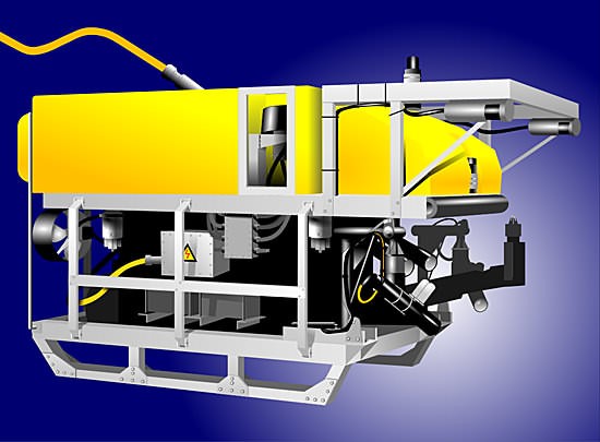 play a key role in the advancement of the world’s economy; one of those machines is the ROV(right).
play a key role in the advancement of the world’s economy; one of those machines is the ROV(right). Exactly who to credit with developing the first ROV will probably remain clouded. However, there are two who deserve credit. The PUV (Programmed Underwater Vehicle) was a torpedo developed by Luppis-Whitehead Automobile in Austria in 1864, but, the first tethered ROV, named POODLE, was developed by Dimitri Rebikoff in 1953. However the American Navy is credited with advancing the technology which started in the 1960’s. Since that time the technology has grown by leaps and bounds and now ROVS play a key role in the exploration of the oceans. Since ROVS can go where no human can go they provided a great deal of aid to the exploration of the ocean. ROVS since their creation have been steadily advancing in their capabilities and as the need for raw materials increase human kind has turned to the ocean for them. As humans explore deeper parts of the oceans ROVS will need to be able to handle the new conditions set forth to them.
A key component to the ROV is its robotic appendage. Whether the appendage is an arm, claw, or some other attachment; they all perform similar tasks. In 1962 the first industrial arm robot - the Unimate - is introduced. It is designed to complete repetitive or dangerous tasks on a General Motors assembly line; this was the start of a new age of technology. Then in 1969 only seven years after the first robotic arm was invented Victor
Scheinman, a Mechanical Engineering student working in the St anford Artificial Intelligence Lab (AIL) creates the Stanford Arm (right). The arm's design becomes a standard and is still influencing the design of robot arms today. Five years After Victor Scheinman created the Stanford Arm, he starts his own company and starts selling the Silver arm, which can put together small parts. In 1981 Takeo Kanade builds the direct drive arm. It is the first to have motors installed directly into the joints of the arm. This change makes it faster and much more accurate than previous robotic arms.
A key component to the ROV is its robotic appendage. Whether the appendage is an arm, claw, or some other attachment; they all perform similar tasks. In 1962 the first industrial arm robot - the Unimate - is introduced. It is designed to complete repetitive or dangerous tasks on a General Motors assembly line; this was the start of a new age of technology. Then in 1969 only seven years after the first robotic arm was invented Victor
Scheinman, a Mechanical Engineering student working in the St
anford Artificial Intelligence Lab (AIL) creates the Stanford Arm (right). The arm's design becomes a standard and is still influencing the design of robot arms today. Five years After Victor Scheinman created the Stanford Arm, he starts his own company and starts selling the Silver arm, which can put together small parts. In 1981 Takeo Kanade builds the direct drive arm. It is the first to have motors installed directly into the joints of the arm. This change makes it faster and much more accurate than previous robotic arms.Today ROVS and the robotic appendages attached to them do many things. Whether the ROV belongs to an oil company, in which case it cleans oil rigs and even searches for oil deposits in the ocean. Or the ROV could belong to a scientific research team, where the ROV collects samples of marine life or mineral deposits for research. No matter what the ROV’s task is, one thing remains the same; the robotic appendage must be able to handle the  situation whether it is from heavy lifting to precise movements of objects the appendage must be able to handle the work load.
situation whether it is from heavy lifting to precise movements of objects the appendage must be able to handle the work load.The MATES competition is designed to promote young students to take part in designing and building ROVS so that there will be future engineers designing the next wave of ROVS. It is important to solve the problem of designing newer and better ROVS so that it is possible to explore the deeper parts of the ocean. To help solve this problem, the user of the solution must be taken into account. The people that would use this robot would be my teammates and I. Each member of the team has his or her own strengths and weaknesses; LB is a strong Xbox gamer and would a great candidate to control both the ROV and arm, LB's only weakness would be his lack of experience in this competition. SD is a another strong candidate to control the ROV and its arm; she is a strong PC gamer as opposed to LB who is a console gamer, SD however has experience at the competition. SD's one weakness is that she is a PC gamer which would require a more difficult control system, which would be difficult to create and use. AF, the final team member is both a PC and console gamer and has experience at this competition before, however, he is not as proficient as SD at PC gaming nor is he as proficient at console gamin as LB is. .
Hazlegreaves, Robert. "ROV." Xara Xone. 23 Sep 2007. Xara Xone Group. 24 Sep 2007
"AUV-ROV-UUV Applications." 23 Sep 2007. Sontek. 24 Sep 2007 .
"Smart Machines." Highlights from the Computer Museum Report . 23 Sep 2007. 24 Sep 2007 .
Design Brief
Design and construct a robotic appendage that will be able to complete any tasks set forth by the MATES competition, which my team of three can operate.
Wednesday, September 19, 2007
MP1 Calender
Week of September 17-21
20. Hand in completed calendar; finish corrections on portfolio, post corrections on blog, and start to redo drawings
21. Continue work on drawings for presentation
Week of September 24-28
24. Finish drawings for robotic arm, scan drawings and send them to mentor
25. Update blog and calendar, start to redo 3d drawings
26. Continue work on 3d drawings, update mentor on progress
27. Finish 3d drawings of arm; send completed drawings to mentor, upload drawings to blog
28. Start preparation for informal presentation, start outline for presentation
Week of October 1-5
1. Finish preparation for presentation, finish outline, update blog
2. Contact mentor for status update, practice for presentation
3. Presentation, hand in Outline and up to date web blog
4. Presentation
5. Presentation
Week of October 8-12
8. Start selection rejection report
9. Continue work on selection rejection report, focusing on imagery for it, update blog
10. Work on the pros and cons of solution one of selection rejection report
11. work on second solutions pros and cons for report
12. work on third solutions pros and cons for report, update blog
Week of October 15-19
15. Finish up selection rejection report and up date mentor on progress
16. Make final corrections and upload selection rejection to blog, update calendar on blog
17. Start to design model, layout all materials needed to create model
18. Start to measure and materials need for model and begin to cut them to size
19. Finish measuring and cutting all materials for model, update blog
Week of October 22- 26
22. Start to attach materials to each other, and contact mentor for update on progress of project
23. Continue to assemble model, update blog
24. Continue with the assembly of model
25. Finish assembly of model, take pictures of it and send to mentor
26. Update blog; start to prepare blog for formal presentation
Week of October 29- November 2
29. Start outline for formal presentation
30. Update blog, continue work on outline, and prepare for presentation
31. Hand in outline, mentor contacts, selection rejection report, and model
1. Presentations
2. Presentations
Week of November 5-9
5. Presentations
6. Update both blog and mentor
7. Start new calendar for MP2
8. Start developmental work
9. Start developmental work
Week of November 12-13
12. Start developmental work
13. Start developmental work
Tuesday, September 18, 2007
Subscribe to:
Posts (Atom)